Printed in The American Tri-Five magazine in Volume 6 : Issue 1
For many, the iconic Tri-Five is one that mimics the race cars of a time since past: nose high, and a straight axle under the front framerails. And ever since the first time a home-grown racer stuck an Econoline axle under his ’55, people have been searching for a better way to accomplish the task.
In modern times, No Limit Engineering has, dare I say, perfected the art of the straight axle with their line of BAG (“Bad Ass Gasser”) products. If you’ve been along with us here at the ATFA for more than a couple years, you’re sure to be familiar with the All American gasser, built by Woody’s Hot Rodz and given away at the 2017 Danchuk Tri-Five Nationals. The All American was perched upon one of No Limit’s BAG chassis, a true work of art. But for the guy who has a good chassis to start with, already has his rear suspension squared away, or simply isn’t looking to go as far as replacing a full chassis, all the attitude is available in a smaller, more inexpensive package that makes up the BAG stub kit.
You’ll see as the article goes on; the BAG stub replaces your factory frame section from just behind the firewall body mount forward. There’s nothing reused, it’s all 100% new. The steering is all figured out from the get-go, utilizing a Vega-style box mounted in a front-steer position, and including all links and rod ends. Doing so keeps the steering link from the box to the opposing spindle as level as possible, and cuts down on bumpsteer, ultimately making for a better driving, better handling straight axle car. As well as the steering being complete, each stub comes with a complete with complete disc brakes, shocks, and all hardware needed for assembly. With options to add Wilwood brakes, Viking double-adjustable shocks, Flaming River Steering box, and more, this stub can easily be tailor-fit for your needs.
The big question is always “well, how is the install?” Follow along, and you’ll see! Note that in our article here, we’ll be showing single sides of the process to conserve page space, and this is a fairly extensive process. We encountered nothing different side-to-side as far as the install process goes, so left to right will receive the same treatment. On to the install!
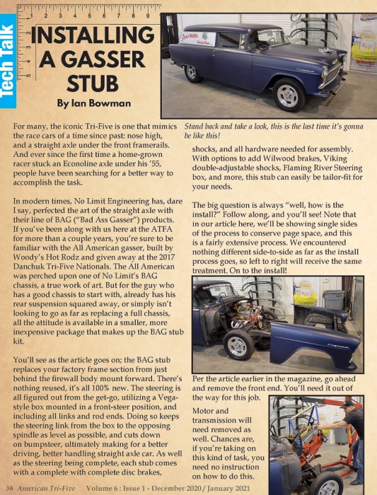
Per the article earlier in the magazine, go ahead and remove the front end. You’ll need it out of the way for this job.
Motor and transmission will need removed as well. Chances are, if you’re taking on this kind of task, you need no instruction on how to do this.
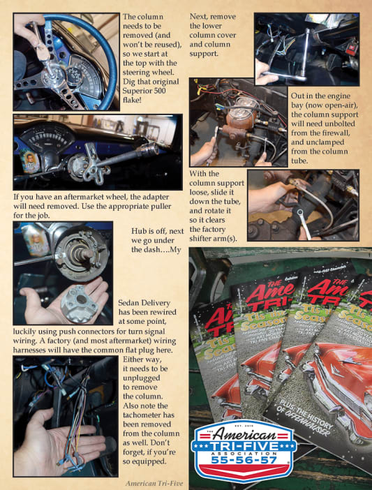
The column needs to be removed (and won’t be reused), so we start at the top with the steering wheel. Dig that original Superior 500 flake!
If you have an aftermarket wheel, the adapter will need removed. Use the appropriate puller for the job.
Hub is off, next we go under the dash….My Sedan Delivery has been rewired at some point, luckily using push connectors for turn signal wiring. A factory (and most aftermarket) wiring harnesses will have the common flat plug here. Either way, it needs to be unplugged to remove the column. Also note the tachometer has been removed from the column as well. Don’t forget, if you’re so equipped.
Next, remove the lower column cover and column support.
Out in the engine bay (now open-air), the column support will need unbolted from the firewall, and unclamped from the column tube.
With the column support loose, slide it down the tube, and rotate it so it clears the factory shifter arm(s). This may require some persuasion, depending on how long it's been in place, or how many layers of paint/grime are on it.
Once the support is out of the way, you can head back inside and pull the column tube out from around the shaft.
Watch the shift levers. They’ll get hung up in the firewall, most likely, and you’ll need to rotate the column to get them through.
Since the steering box on this one is pretty well shot, and I didn’t want the extra work of disassembling all the steering, I chose to cut the steering column shaft to make life easy. This is surprisingly easier than you’d probably think, and only further solidifies that grinding a factory steering shaft into a double-D to use with an aftermarket steering box is a terrible idea.
Helpful hint: Gas will find the lowest point in the system (thanks to gravity). If you forgot that you had a half a tank of fuel (like I did), draining it and removing the main line, as well as the brake lines, before cutting and welding up front is a solid idea.
…and there it is. As it ships from No Limit, the stub as ordered will have the steering box and link, as well as the shocks, not pictured as this was a display model.
The stub will need to be broken down to just the bare rails, at any rate. Front leaf spring bolt nuts are first.
….then the shackle bolts and the retainer.
The shackle itself can then be removed, along with the bushings, and set aside for safe keeping.
With the rear shackles removed, pull the front leaf spring bolts.
And just like that, your stub is free!
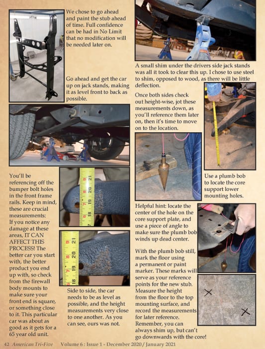
We chose to go ahead and paint the stub ahead of time. Full confidence can be had in No Limit that no modification will be needed later on.
Go ahead and get the car up on jack stands, making it as level front to back as possible.
You’ll be referencing off the bumper bolt holes in the front frame rails. Keep in mind, these are crucial measurements: If you notice any damage at these areas, IT CAN AFFECT THIS PROCESS! The better car you start with, the better product you end up with, so check from the firewall body mounts to make sure your front end is square, or something close to it. This particular car was about as good as it gets for a 65 year old unit.
Side to side, the car needs to be as level as possible, and the height measurements very close to one another. As you can see, ours was not.
A small shim under the drivers side jack stands was all it took to clear this up. I chose to use steel to shim, opposed to wood, as there will be little deflection.
Once both sides check out height-wise, jot these measurements down, as you’ll reference them later on, then it’s time to move on to the location.
Use a plumb bob to locate the core support lower mounting holes.
Helpful hint: locate the center of the hole on the core support plate, and use a piece of angle to make sure the plumb bob winds up dead center.
With the plumb bob still, mark the floor using a permanent or paint marker. These marks will serve as your reference points for the new stub. Measure the height from the floor to the top mounting surface, and record the measurements for later reference. Remember, you can always shim up, but can’t go downwards with the core!
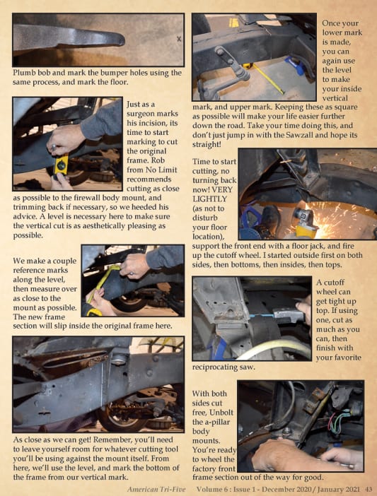
Plumb bob and mark the bumper holes using the same process, and mark the floor.
Just as a surgeon marks his incision, its time to start marking to cut the original frame. Rob from No Limit recommends cutting as close as possible to the firewall body mount, and trimming back if necessary, so we heeded his advice. A level is necessary here to make sure the vertical cut is as aesthetically pleasing as possible.
We make a couple reference marks along the level, then measure over as close to the mount as possible. The new frame section will slip inside the original frame here.
As close as we can get! Remember, you’ll need to leave yourself room for whatever cutting tool you’ll be using against the mount itself. From here, we’ll use the level, and mark the bottom of the frame from our vertical mark.
Once your lower mark is made, you can again use the level to make your inside vertical mark, and upper mark. Keeping these as square as possible will make your life easier further down the road. Take your time doing this, and don’t just jump in with the Sawzall and hope its straight!
Time to start cutting, no turning back now! VERY LIGHTLY (as not to disturb your floor location), support the front end with a floor jack, and fire up the cutoff wheel. I started outside first on both sides, then bottoms, then insides, then tops.
A cutoff wheel can get tight up top. If using one, cut as much as you can, then finish with your favorite reciprocating saw.
With both sides cut free, Unbolt the a-pillar body mounts. You’re ready to wheel the factory front frame section out of the way for good.
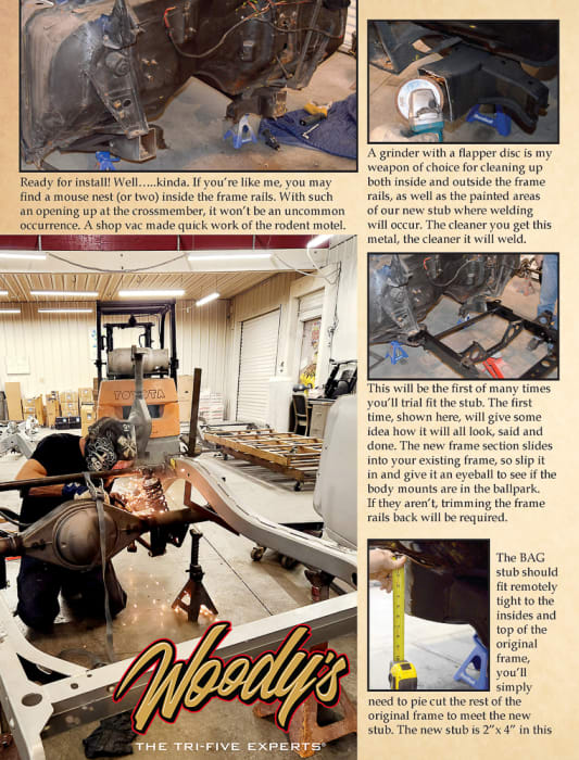
Ready for install! Well…..kinda. If you’re like me, you may find a mouse nest (or two) inside the frame rails. With such an opening up at the crossmember, it won’t be an uncommon occurrence. A shop vac made quick work of the rodent motel.
A grinder with a flapper disc is my weapon of choice for cleaning up both inside and outside the frame rails, as well as the painted areas of our new stub where welding will occur. The cleaner you get this metal, the cleaner it will weld.
This will be the first of many times you’ll trial fit the stub. The first time, shown here, will give some idea how it will all look, said and done. The new frame section slides into your existing frame, so slip it in and give it an eyeball to see if the body mounts are in the ballpark. If they aren’t, trimming the frame rails back will be required.
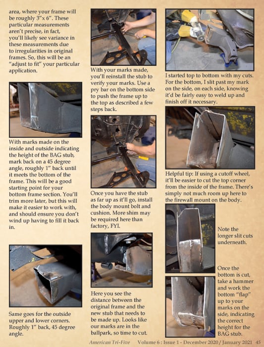
The BAG stub should fit remotely tight to the insides and top of the original frame, you’ll simply need to pie cut the rest of the original frame to meet the new stub. The new stub is 2”x 4” in this area, where your frame will be roughly 3”x 6”. These particular measurements aren’t precise, in fact, you’ll likely see variance in these measurements due to irregularities in original frames. So, this will be an “adjust to fit” your particular application.
With marks made on the inside and outside indicating the height of the BAG stub, mark back on a 45 degree angle, roughly 1” back until it meets the bottom of the frame. This will be a good starting point for your bottom frame section. You’ll trim more later, but this will make it easier to work with, and should ensure you don’t wind up having to fill it back in.
Same goes for the outside upper and lower corners. Roughly 1” back, 45 degree angle.
With your marks made, you’ll reinstall the stub to verify your marks. Use a pry bar on the bottom side to push the frame up to the top as described a few steps back.
Once you have the stub as far up as it’ll go, install the body mount bolt and cushion. More shim may be required here than factory, FYI.
Here you see the distance between the original frame and the new stub that needs to be made up. Looks like our marks are in the ballpark, so time to cut.
I started top to bottom with my cuts. For the bottom, I slit past my mark on the side, on each side, knowing it’d be fairly easy to weld up and finish off it necessary.
Helpful tip: If using a cutoff wheel, it’ll be easier to cut the top corner from the inside of the frame. There’s simply not much room up here to the firewall mount on the body.
Note the longer slit cuts underneath.
Once the bottom is cut, take a hammer and work the bottom “flap” up to your marks on the side, indicating the correct height for the BAG stub.
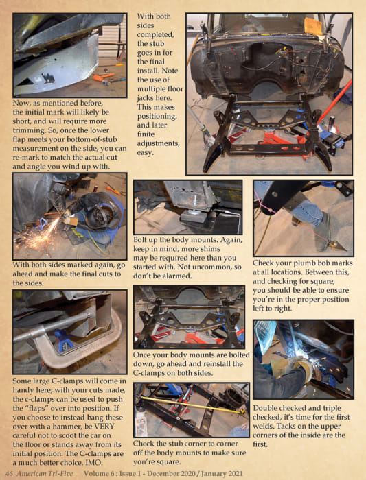
Now, as mentioned before, the initial mark will likely be short, and will require more trimming. So, once the lower flap meets your bottom-of-stub measurement on the side, you can re-mark to match the actual cut and angle you wind up with.
With both sides marked again, go ahead and make the final cuts to the sides.
Some large C-clamps will come in handy here; with your cuts made, the c-clamps can be used to push the “flaps” over into position. If you choose to instead bang these over with a hammer, be VERY careful not to scoot the car on the floor or stands away from its initial position. The C-clamps are a much better choice, IMO.
With both sides completed, the stub goes in for the final install. Note the use of multiple floor jacks here. This makes positioning, and later finite adjustments, easy.
Bolt up the body mounts. Again, keep in mind, more shims may be required here than you started with. Not uncommon, so don’t be alarmed.
Once your body mounts are bolted down, go ahead and reinstall the C-clamps on both sides.
Check the stub corner to corner off the body mounts to make sure you’re square.
Check your plumb bob marks at all locations. Between this, and checking for square, you should be able to ensure you’re in the proper position left to right.
Double checked and triple checked, it’s time for the first welds. Tacks on the upper corners of the inside are the first.
Head back out to check the height on your mount holes. Note the use of the floor jack; this will make nailing the height especially easy.
Once your heights are correctly verified, apply more tacks to the inside of the frame rails. This will be sufficient to keep everything in place.
Re-check square again to ensure tacks didn’t pull it one way or another. Remember, its easier to grind off a few tacks than it is to cut an entire weld free, so don’t be afraid to verify your measurements multiple times.
With your measurements verified one last time, go ahead and fully weld the insides of both frame rails, rolling over onto the upper section, as well as a tack or two to the outer sides.
Hammer time! Give the frame rail a couple taps to get the sides and bottom as close as possible. Again, try to keep from scooting the car over at all. Helpful hint: Some heat applied properly will reduce effort here, and cut down on chances of movement.
With the outsides and bottoms fitting nicely, go ahead and weld them up completely, as well as the outer part of the top, as you’ll most likely need to come in from the outside to access it.
We also chose to reinforce (aka “plate”) the bottom of the kickups from the original frame to the BAG stub for added strength. No Limit recommends doing this as well, so we heeded the advice. Use cardboard to make a template, and cut a piece of 1/8-1/4” stock to fit the bill. If you see fit, you could plate the top as well.
Break the flapper back out to clean up the mounting surfaces for the plates. Again, cleaner the surface, the better the weld.
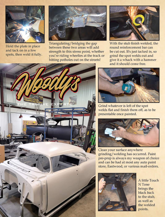
Hold the plate in place and tack on in a few spots, then weld it fully.
Triangulating/bridging the gap between these two areas will add strength to this stress point, whether you’re riding wheelies at the track or hitting potholes out on the streets!
With the stub finish welded, the round reinforcement bar can be cut out. It's just tacked in, so grind the spot welds out and give it a whack with a hammer and it should come free.
Grind whatever is left of the spot welds flat and finish them off, as to be presentable once painted.
Clean your surface anywhere grinding/welding has occurred. Paint pre-prep is always my weapon of choice and can be had at most any auto paint store, Eastwood, or various mail-orders.
A little Touch N Tone brings the black back to the stub, as well as the welded points.
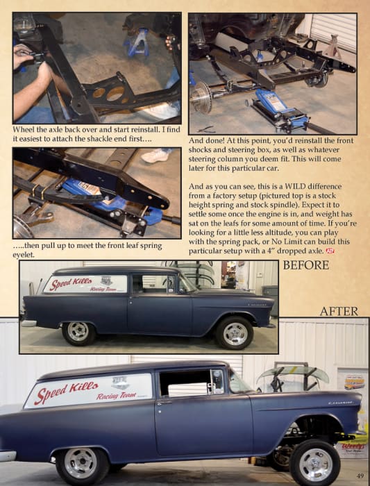
Wheel the axle back over and start reinstall. I find it easiest to attach the shackle end first….
…..then pull up to meet the front leaf spring eyelet.
And done! At this point, you’d reinstall the front shocks and steering box, as well as whatever steering column you deem fit. This will come later for this particular car.
And as you can see, this is a WILD difference from a factory setup (pictured top is a stock height spring and stock spindle). Expect it to settle some once the engine is in, and weight has sat on the leafs for some amount of time. If you’re looking for a little less altitude, you can play with the spring pack, or No Limit can build this particular setup with a 4” dropped axle.
Browse our Gasser exclusive items here.